Measurement scheme for electric vehicle drive system
I. Introduction
With the increasing attention to energy and environmental issues, electric vehicles are developing rapidly due to their advantages such as being clean and pollution-free, having high energy efficiency, low noise, and diverse energy sources. As a means of transportation, electric vehicles operate in a complex and changeable working environment. Their motor drive systems need to meet performance requirements such as high reliability, high efficiency, good adjustment performance, and low cost. Therefore, the testing of electric vehicle motor drive systems is an important research content. The following scheme uses the British Voltech PM6000 high-precision power analyzer as the main measurement equipment to provide a detailed description of the electric vehicle motor drive system. As shown in Figure 1, the quantities to be tested for the motor drive system are: four channels of current and four channels of voltage of the motor controller, including the input DC bus voltage and current and the output three-phase AC voltage and current values; the output torque and speed of the motor.
II. Scheme configuration list
- One British Voltech PM6000 four-channel high-precision power analyzer (including four 1A shunts, with a basic accuracy of 0.02%).
- Three Voltech CT1000 closed-loop current transformers (for AC current testing, with two ranges: 100:1 or 1000:1. For small currents, 100:1 can be used. For large currents, 1000:1 can be used. The maximum primary side current allowed is 1000 Arms, with an accuracy of 0.2%).
- One LEM current sensor IT400-S (for both AC and DC use. The maximum primary side current allowed is 400 Arms, with an accuracy of 0.0033%).
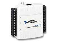
- The NI USB6009 is a multifunctional data acquisition card produced by NI. In this scheme, it is used to collect the analog signals transmitted by the speed and torque sensors, and then connect to the computer with the VPAS software installed through its USB interface to collect speed and torque data.
- One set of Voltech VPAS software.
- One NI USB6009 multifunctional data acquisition box (used to calculate test torque, speed, efficiency, etc.).
- One set of speed and torque sensors (to be prepared by the customer).
One computer (to be prepared by the customer).
III. Configuration description
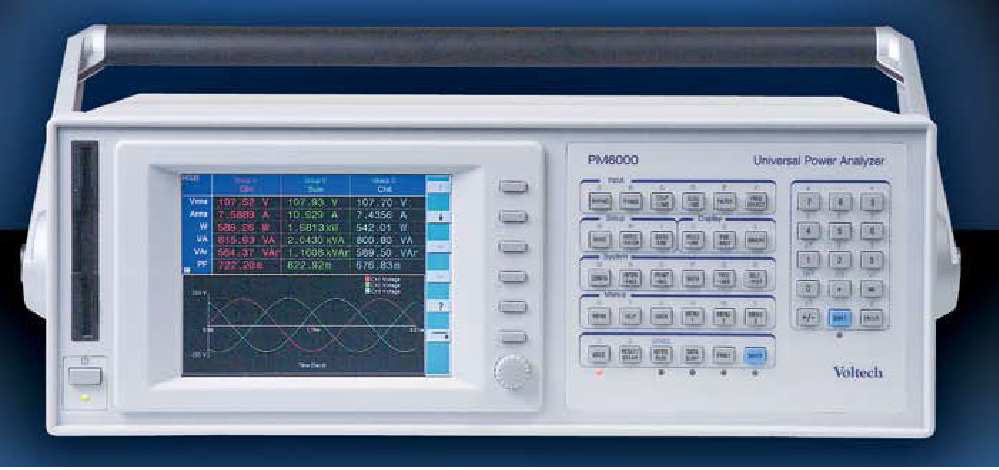
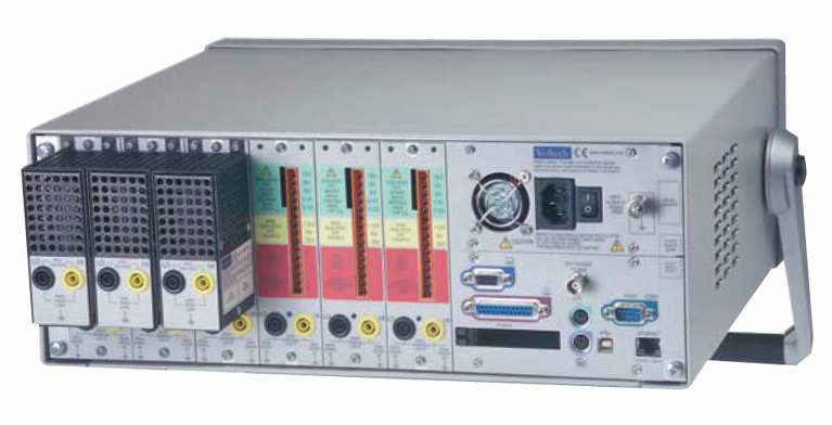
The PM6000 is a multi-channel high-precision power analyzer developed and produced by Voltech in the UK. It can be configured with up to six measurement channels. The basic accuracy is 0.02%. The bandwidth is up to 10 MHz, and the sampling rate is up to 40 MSPS (millions of samples per second). The excellent common-mode signal suppression ability ensures high accuracy and reliability of measurement. The clear color display screen and intuitive menu system make the operation more convenient. The provided Math calculation function greatly improves the practicability of the instrument, enabling customers to perform calculations in various ways, such as the conversion efficiency of input and output. The PM6000 can directly input a voltage of 1400 Vrms. For the current part, there are 30 A shunts or 1A shunts to choose from. For testing small currents, a 1A shunt can be selected to accurately measure the small current signals converted by current transformers and Hall sensors. If other product lines need to frequently test currents below 30A and have high requirements for testing accuracy, a 30A shunt can be selected and the current is directly input for testing. For the rear structure diagram of the PM6000, see Figure 3. In terms of instrument interfaces, the PM6000 has RS232, Ethernet port, VGA display interface, printer interface, and P/S 2 keyboard and mouse interfaces.
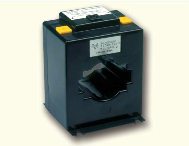
The Voltech CT1000 current transformer adopts a closed-loop design with an accuracy of more than 0.2%. It is used to measure AC current. It has two ranges: 100A and 1000A, and can measure a maximum current of 1000 Arms. The CT1000 does not need separate power supply, is simple and convenient to use, and has high cost performance.
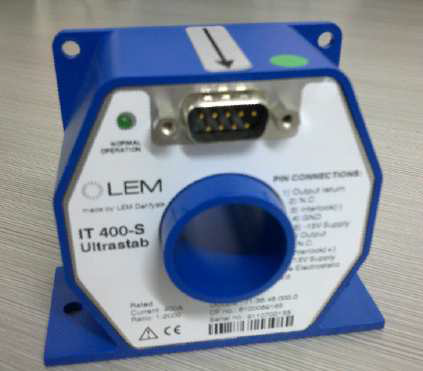
The LEM IT400-S current sensor is a high-precision, wide-bandwidth (DC~100KHZ), closed-loop current sensor with an accuracy of 0.0033%. It is used for AC and DC current testing, and the maximum measured current is 400 Arms. It requires ±15V voltage supply. In addition, if a larger current needs to be measured, IT600-S or IT700-S can be selected.
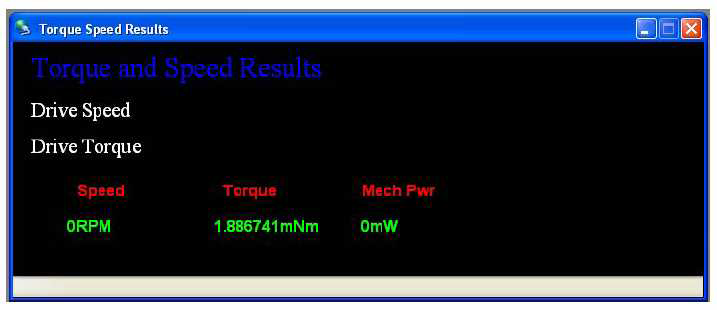
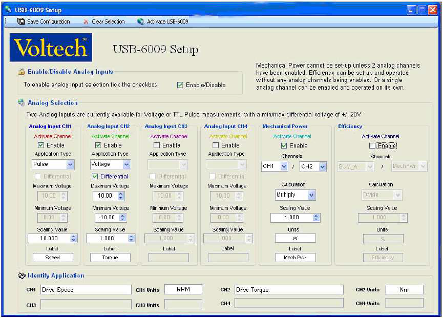
The VPAS analysis software provides full control and data acquisition capabilities for the PM6000 in a computer environment. The software operates through the Ethernet or R232 interface of the PM6000. The computer can be directly connected to a PM6000 or connected through a standard local area network, providing great flexibility. The software also integrates auxiliary analog quantity testing, such as torque and speed, providing convenient calculations and data recording for all test items.
- The speed and torque sensor is used to convert mechanical energy into analog electrical signals and then transmit them to the NI USB6009 multifunctional data acquisition card.
One computer is used to install the Voltech VPAS software.
IV. Test description
- Electrical parameter measurement part.
Completed by the PM6000 power analyzer combined with corresponding Hall sensors and current transformers. The specific wiring method is as follows:
Connection method | PM6000 measurement channel | Test item
DC bus input | Measurement channel 1 | DC voltage, DC current, power
AC A output | Measurement channel 2
AC B output | Measurement channel 3
AC C output | Measurement channel 4
Voltage (effective value, peak value), current (effective value, peak value), power (active, reactive, apparent power), crest factor, power factor, harmonics (voltage, current, power), total harmonic distortion
Math function (built-in function of PM6000) | Input-output conversion efficiency (real-time efficiency) - Analog quantity test (speed, torque, mechanical power).
The analog signal converted by the speed and torque sensor is connected to the NI USB6009, and then connected to the computer with the VPAS software installed through a USB cable. Use the VPAS software to display speed and torque and calculate mechanical power.
V. Supplementary description of the scheme
The above scheme only configures four test channels (i.e., PM6000-4). If it is necessary to test high-power inverter products, two additional test channels (i.e., PM6000-6) need to be added, and at the same time, three more CT1000s need to be added. With PM6000-6, all synchronous tests of high-power inverters can be realized.
Kevin Wang
Technology Department
Bestern Asia Industrial Limited

 Amid Power Supply Localization
 Power Solutions for Telecom, M
 CDR-1321-1M1 1300W DC/DC Power
 Huawei ETP4860-B1A2 power supp


